LM317 Application Notes Example
Table of Contents
I was messing around a while ago to modify my Norcal QRP Club Power Meter kit so that I could power it from the shack DC supply. The kit takes a 9V battery by default and I wanted to power it from the 13.8V shack supply. I didn’t have an LM7809 handy but I did have an LM317.
I also didn’t want to mess around with a variable trim on the supply so I looked at the oddball combination of resistors that I had on hand and decided to draw the curves for the LM317 against all the combinations I could make fairly easily (parallel and series for any two).
The application note for the LM317 shows that a typical application is:
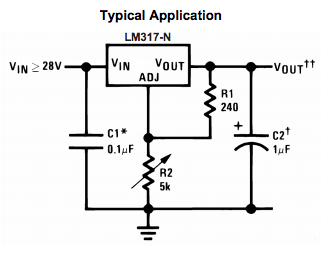
The output voltage $V_{out}$ is given by the formula:
$$ V_o = 1.25 ( 1 + \frac{R_2}{R_1}) + I_{adj}R_2 $$
This defines a family of curves for each chosen $R_1$ (although only values in the range $200\Omega - 280\Omega$ are appropriate. Selection of $R_2$ will determine the output voltage.
I whipped up a quick python script at github that uses matplotlib to show the curve family and plot the output voltage error boxes (presuming 5% tolerance resistors). I make no apologies for the script – it is a bit of a hack from a time I really didn’t know python yet.
Here’s the result (click for PDF):
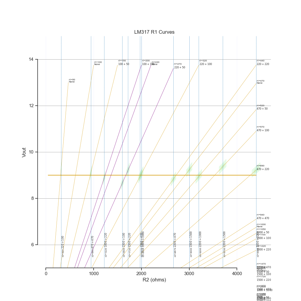
I selected the appropriate parts ($R_1 = 270, R_2 = 1720$) and built it into the case for the meter. Has been working great ever since.
comments powered by Disqus