PWM Controller Hacking
Table of Contents
Enough people have asked about it so I figured I would write up my PWM controller that I’ve hacked together. Ultimately I’d like to make it ATtiny powered and I might have made a mistake by getting the analog version working - as it works well enough and has removed the pressing need to build the digital version.
I managed to source everything at Radio Shack except the MOSFET. I picked that up at a local, terribly overpriced component supply store. I also purchased the pot there, simply because I liked the physical size of it - RS had a reasonable replacement. In choosing your N-channel MOSFET, make sure you select one that is fully ‘on’ at the level generated by the 555 circuit (not a problem as the signal is around 12V peak-to-peak) and has a very low $$R_{ds(on)}$$. If you are planning to use an ATtiny for the controller (instead of the 555) then you need to select a MOSFET with an appropriately low threshold voltage, such as the STP36NF06L.
The schematic is a modification of another circuit I found online at sentex.ca. There is an alternate PWM 555 circuit (similar) at [dprg.org] (http://www.dprg.org/tutorials/2005-11a/index.html), but I did not like the lack of EMF/flyback protection in that design - effectively they are very similar circuits.
I modified the schematic slightly - as we are not controlling a large inductive load and I installed a much smaller capacitor for C3, just to take the edge off the PWM wave-form.
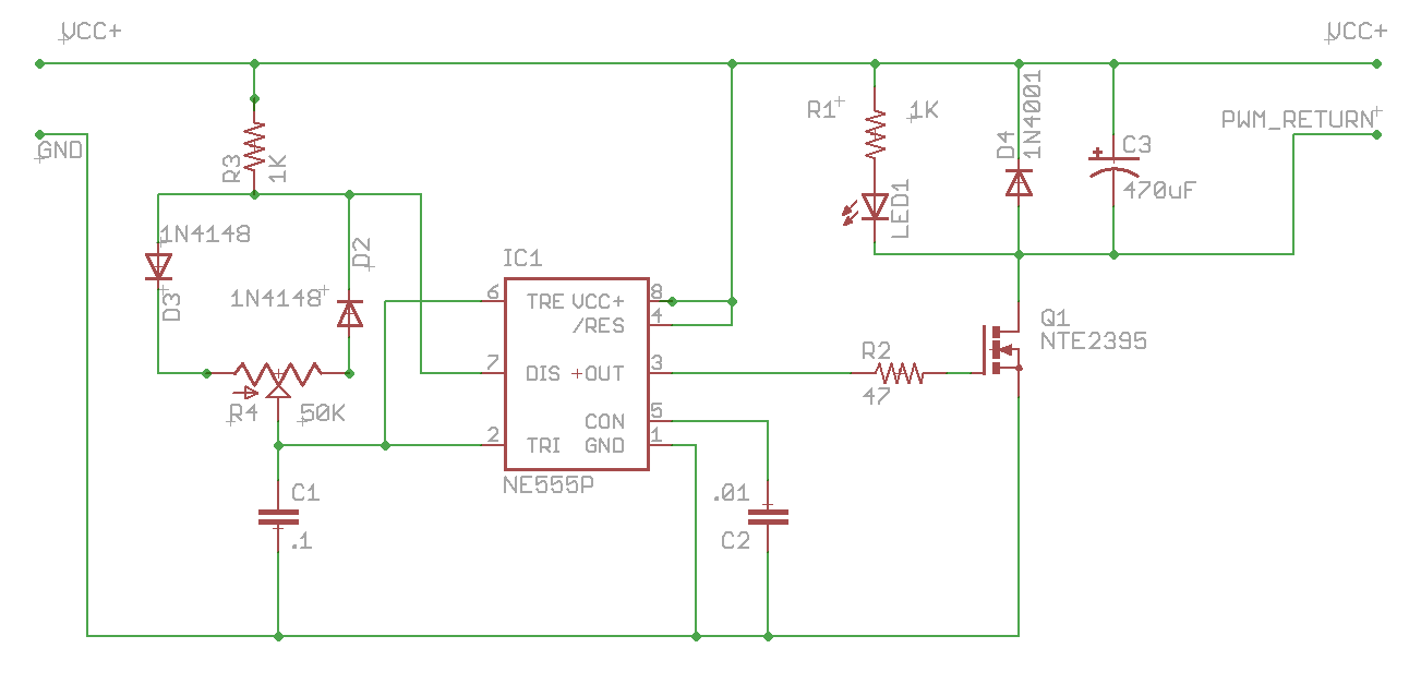
LED1 is optional (along with R1) - and in my case I used a Radio Shack 12V ‘LED indicator’ (see photos). If you wanted to do this yourself, select R1 to match LED1 at a 14V supply voltage. I recommend R1/LED1 as it permits a quick glance in the mirror to confirm that the controller is active and the power level setting. D4 is simply providing a path for any collapsing field energy, but I am not sure there is much in a resistive load like a heated vest. I used a very small cap for C3 - simply because I didn’t have a 470uF cap lying around and I was impatient. Seems to be working fine for me.
The NTE2395 data sheet mentions that $$R_{ds(on)}$$ is 0.028$$\Omega$$ so it doesn’t dissipate much power as heat
- an important consideration.
Power enters via the right-hand pair of contacts (Vcc/GND) and the vest / grips plug into the upper right contacts (Vcc/PWM_Return). The design is switching the power return circuit - effectively modulating the ground connection.
At these voltages and power levels, I have no concerns around that approach - and it a common technique (vs high-side switching).
Here is the parts list for the build, all caps at 20V rating and all resistors are 1/4W:
| Part | Value | Former RS Part No |
|---|---|---|
| C1 | .1 | 272-135 |
| C2 | .01 | |
| C3 | 470uF | 272-1030 |
| D2 | 1N4148 | |
| D3 | 1N4148 | |
| D4 | 1N4001 | |
| IC1 | NE555P | |
| LED1 | See text | |
| Q1 | NTE2395 | N/A |
| R1 | 1K (see text) | 271-1321 |
| R2 | 47 | |
| R3 | 1K | 271-1321 |
| R4 | 50K |
The schematic was built up on Radio Shack breadboard styled protoboard, with point-to-point wiring. Nothing to write home about, in some cases, I put insulation on leads and used the components to assist with the hook-up. (See obvious diode D2/D3 as examples). The assembly was housed in a small Radio Shack plastic enclosure.
Here’s a shot of the nearly assembled unit:
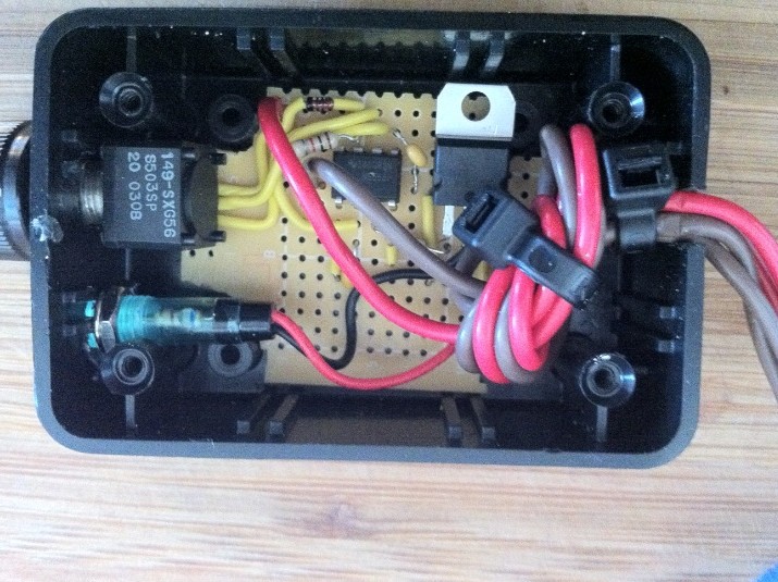
Note the generous overhand knot and ties for strain relief where the power cables exit the case.
The Radio Shack indicator LED is in the lower left, beneath the potentiometer. I haven’t assembled anything in years, so it is a little messy in there.
The connectors are a $2 towing extension cable from the local auto parts store - SAE connectors on either end happen to fit the vest I’m controlling. A single piece of red heat shrink tubing on one of the connectors is used to mark the ‘hot’ side (vs the vest side). I haven’t thought it through, but it looks like hooking it up backwards would not do any damage and just leave it inoperative until swapped around.
Here’s a top view for scale:
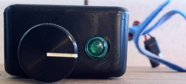
If I was doing this again, I’d consider using a multi position rotary switch with discrete resistor values instead of the pot. It would then be a case of clicking a setting and knowing it would stay set. I would also consider a bypass switch that forced the unit into bypass - assuring 100% power transfer. This might not really be needed, but it would make me feel better. To work around the ease with which the knob turns, I plan to jam a large o-ring under the dial to drag on the case. This would also add weatherproofing. The entire unit fits snugly under a waist adjustment buckle on my riding suit so is held in place with the blue velco in seen in the photo. A small pass-through in the suit pants pocket allows this to live outside and control the heated vest on the inside. I highly recommend the Aerostich Kanetsu Electric Vest.
Overall it is ugly, but it works. And even at Radio Shack prices, it was far cheaper than a commercial product - not to mention satisfying to put together.
comments powered by Disqus